Early in 1963 the Independent Television Authority owns and operates 22 transmitting stations, providing programmes for 96 per cent of the whole population of the United Kingdom. Eighteen of these stations have a full engineering staff; two are semi-manned and two are unmanned satellite stations.
The eighteen fully-manned stations are each equipped with two similar sets of transmitters, each set composed of one vision and one sound unit. Depending upon the power required to be fed to the aerials, all four transmitters may be worked with the vision and the sound pairs in parallel, or one vision and one sound transmitter only. The station equipment includes apparatus for the generation of vision and sound signals for test purposes, and four stations have telecine to provide emergency programmes. The transmitters are connected to studio centres by a network of vision and sound links.
The satellite stations receive programmes on one channel from a “parent” station which, after amplification, are re-radiated on another channel; they are supervised and controlled by the “parent” station.
Vision and Sound Network
A network of vision and sound circuits provides the links between the various ITV areas and between the studio centres and the ITA’s transmitters. This network is rented by the Authority from the General Post Office. The vision circuit totals about 3,100 miles, about half of which is built up of microwave radio systems and half by underground coaxial cables.
To ensure high quality transmission the circuits frequently have a band width equivalent to that required for about 700 simultaneous telephone conversations.
To carry signals to the more remote transmitting stations and to meet short-notice requirements, the Authority has itself installed a number of microwave links which are fed by an “off air” signal received from another transmitter.
ITV’s Technical Development
Independent Television programmes are produced and presented from more than sixty studios in centres at London, Manchester, Birmingham, Glasgow, Belfast, Cardiff, Bristol, Southampton, Dover, Newcastle, Carlisle, Aberdeen, Norwich, Plymouth and the Channel Islands. The total working floor area of these studios is over 170,000 sq. ft., ranging in size up to 14,000 sq. ft. A complex array of technical equipment, cameras, lighting and sound systems is brought into operation by highly skilled staffs. Details of a few of the many technical advances made by the Independent Television programme companies are contained in pages 16-47.
The ITA and the programme companies participate in major national and international conferences on technical aspects of television. As members of the European Broadcasting Union, they are in regular contact with the broadcasting organisations of other countries and, wherever possible, render assistance and advice.
The programmes produced by a combination of artistic and technical skills in the studios are fed to the ITAs stations in the form of television signals. The operation of the stations which transmit the signals to viewers is described in. the pages that follow.
The day at one of the Authority’s transmitting stations normally begins at 8 a.m. and ends soon after midnight, but when necessary work continues throughout the 24 hours.
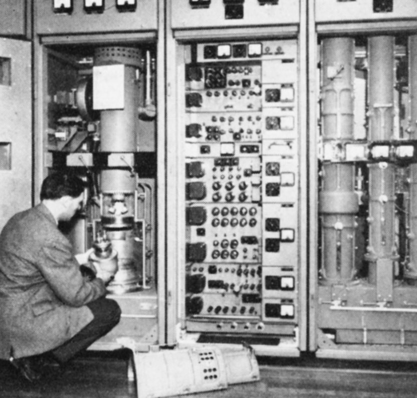
From the arrival at the transmitter of the morning shift of two or three engineers there is about two hours before due station goes on the air at 10 a.m. The most important task is to prove that the two sound and two vision transmitters are fully operational. The power output, frequency response, linearity, noise content and so on must be checked, involving the use of complex and specialised test equipment.
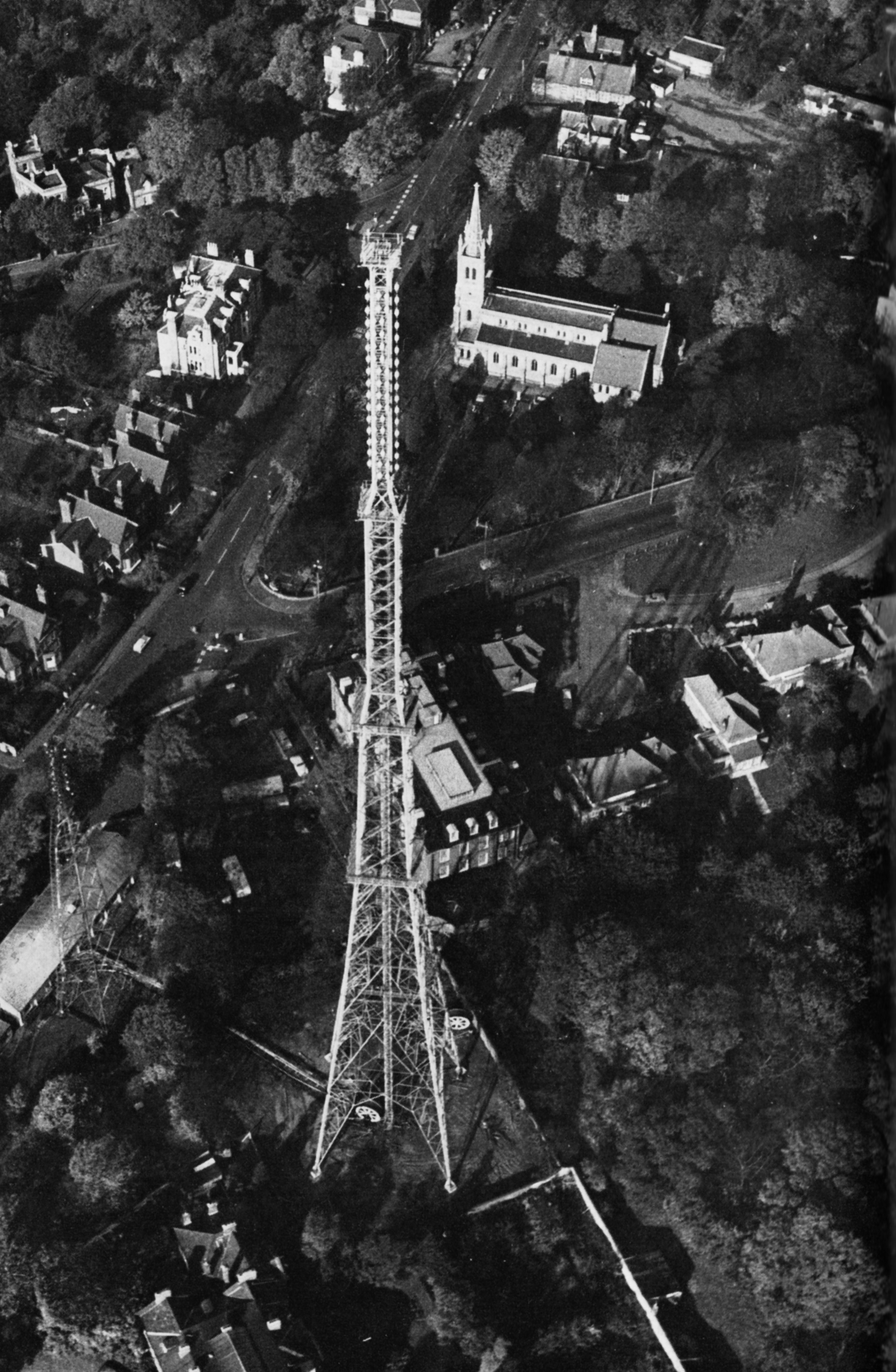
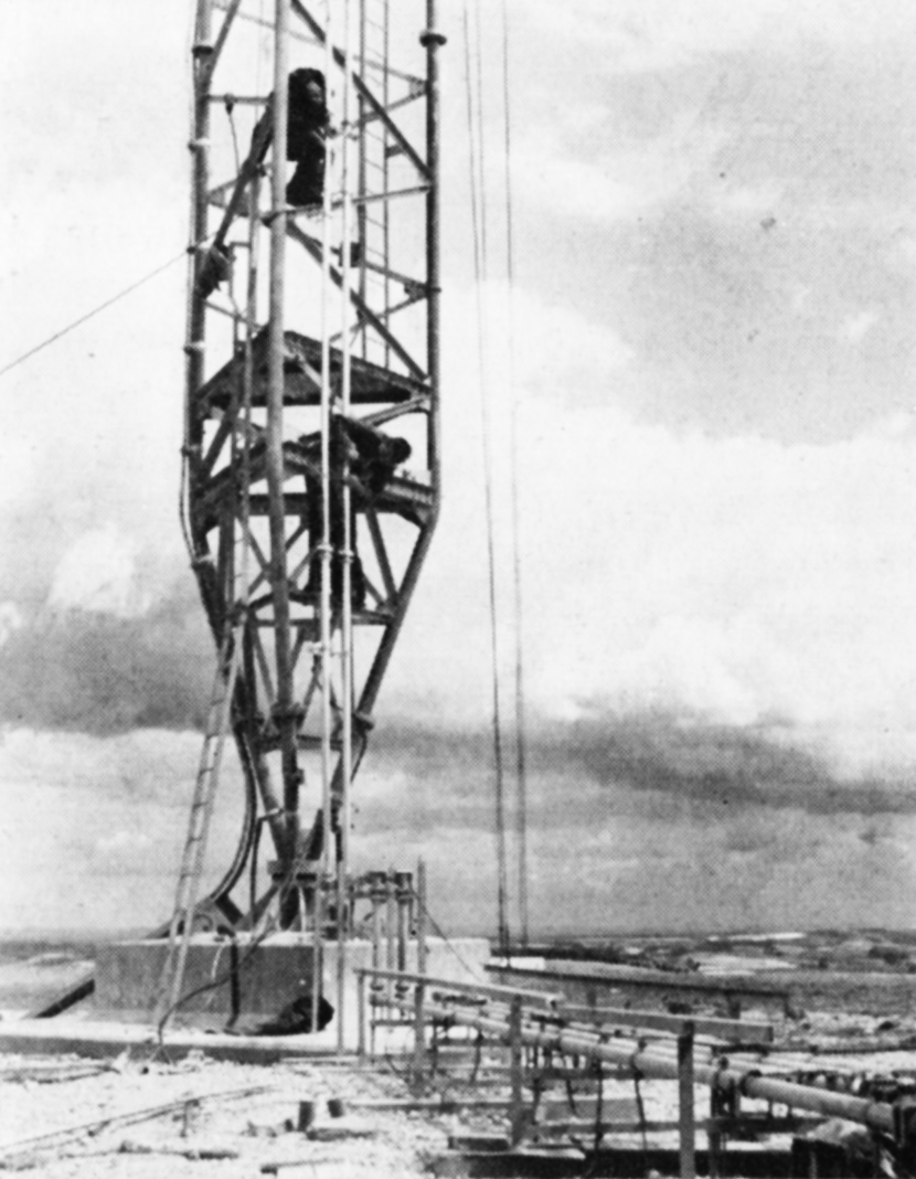
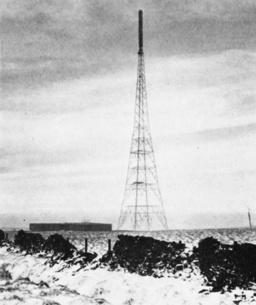
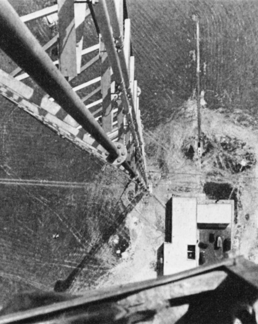
The masts and towers, which vary in height from 450 ft. to 1,000 ft., must be ascended regularly by riggers and climbing electricians to check the structure, aerials, feeder systems, aircraft obstruction lights, the aerial de-icing heaters or plastic covers which prevent ice formation on aerials, and other fittings. Certain of this work can only be done when the transmitters are closed down and, in consequence, it is performed between dawn and 10 a.m.
Trade Transmissions
On weekdays from 10 a.m. a regular schedule of transmissions is provided, primarily for the benefit of the retail trade. The pattern is as follows:
          Vision             Sound
10.00     Test Card “C”      400 c.p.s. tone
10.05           “            Silence
10.06           “            Music
10.30     Still Scene        400 c.p.s. tone
10.35           “            Silence
10.36           “            Music
10.45     Test Card “C”       “
11.00     Still Scene        400 c.p.s. tone
and so on until 15 minutes before the start of programmes. A similar schedule is observed by the BBC, but when the ITA stations are showing a test card the BBC displays a scene. Programme commitments permitting, this ensures that during test periods the trade are able to see a test card on one or other channel at any time. The test card and the sound are used by the trade for the alignment of aerials, and for setting-up and checking receivers. The still scenes are used for receiver demonstration purposes. The short intervals of silence in sound are for checking the receiver noise level.
Adjusting the trade transmission picture
An aerial array on the new Croydon mast
Monitoring duty in the control room
During trade transmissions much work is undertaken at the stations. If only one transmitter unit is in operation certain routine maintenance work is possible on the other, and this work – which according to a schedule may be of minor or major magnitude – is always to be done. In this way equipment is held at a high operational standard so that the maintenance work is very largely of a preventive nature. A typical station uses 1,500 valve sockets and when new valves of the largest and most powerful size are delivered these must be tested under working conditions. Altogether some 200 different types of valve are used.
The majority of stations are served by the various Electricity Supply undertakings by two differently routed feeders, one standby for the other. Where this is not possible, a diesel-driven alternator generally supplements a single feeder, and to maintain it in known running order it is used to power the station during trade transmissions.
Each vision and sound transmitter generates a carrier wave upon which is emplanted the signal from the camera or the microphone. It is this carrier which conveys the signals from the transmitting aerial, through the ether, to the viewers aerials and receivers. Because ether space is limited the Authority’s Band III transmitters share channels and in consequence the carrier wave frequency must be very constant, to an accuracy of ±2.5 parts in a million. It is, of course, necessary regularly to measure the carrier wave frequencies and, in the Authority, this is done at two of the transmitting stations, Lichfield and Black Hill. At these two stations, before 10 a.m. or at midday, the transmitters are switched off and the transmitting aerials at the top of the 1,000 ft. masts are used as receiving aerials for the other transmitters which are located around them – some up to 200 miles away – and the received carriers are measured by special equipment.
On certain days of the week comprehensive checking of the national vision and sound links, and local sections, is undertaken. Test signals are principally originated either in London or Manchester and pass over the network to all centres where they are measured and recorded. Each test occupies one to two hours from 10.30 a.m.
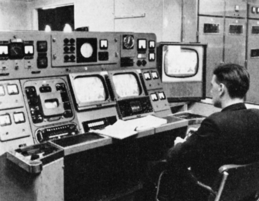
Picture and sound quality are constantly checked
The base of a 1,000-ft. mast
A log is maintained throughout transmission
Daily Programmes
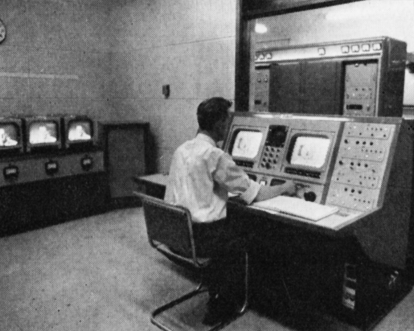
The time of commencement of the daily programmes depends upon the day of the week and the location of the transmitter, but the pattern is similar. The first programme may be for schools, a racing outside broadcast, or a lunch-hour feature, and it may be followed by other items interspersed with trade transmissions before the commencement of the continuous evening schedule. Prior to any programme the links between studio and transmitter must be proved by the passing of test signals in vision and sound, and transmitters must be adjusted to the correct modulation condition. Studios, G.P.O. switching centres and transmitters must work to a common time standard to the nearest second, and this is achieved by all concerned setting clocks to TIM. The final precaution before moving into programme is to check standby equipment in sound and vision – disc turntables, tape recorder, telecine (where provided), and caption scanner.
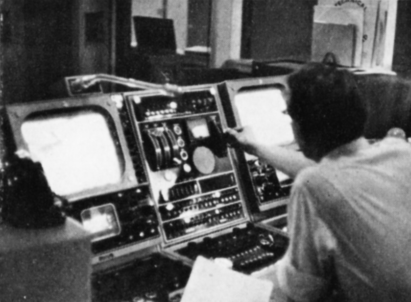
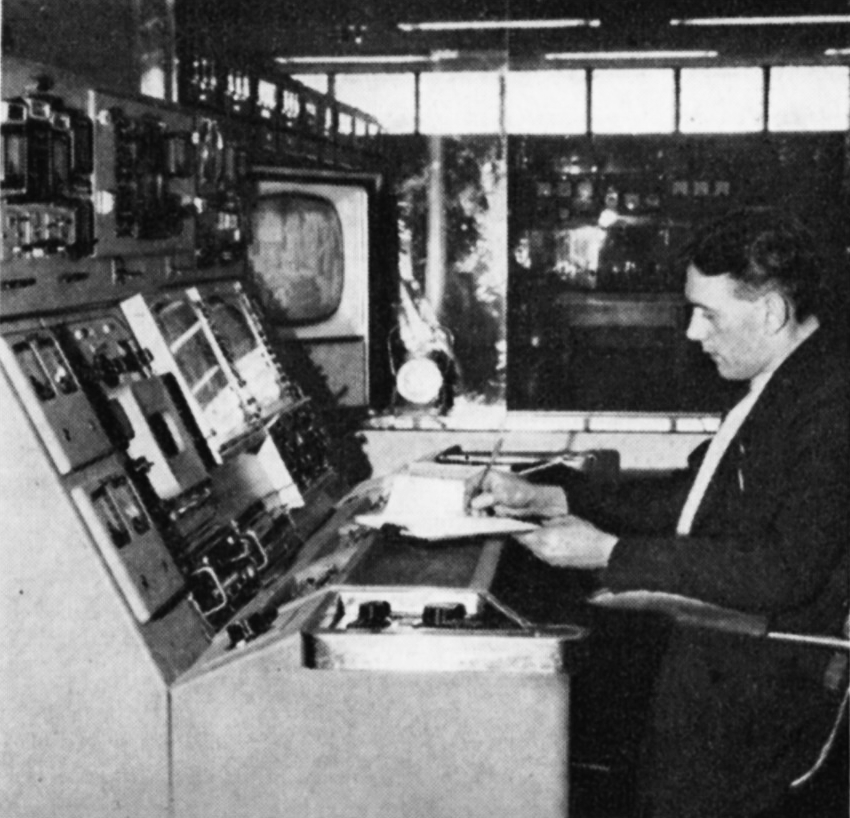
Once programmes have begun, the transmitter control room is the focal point for operations. Picture and sound must be continuously monitored for technical quality, and any point of interest noted in a log. For monitoring to be performed at a worthwhile standard, in vision a considerable knowledge of studio techniques and equipment is needed, such as an appreciation of the special characteristics of camera tubes, videotape recorders, and film. In sound, in addition to quality checking, each type of programme – music, variety or talks -should conform to a specified dynamic range.
It is important for the control room engineer to ensure that the signals suffer no degradation in passing through his station equipment, and this means that at least two picture monitors must be observed, which display the received signal and the transmitted signal; if a satellite transmitter is tied to the staffed station this also must be monitored.
Outside the control room, there is regular checking of all equipment, of the working temperature of bearings of rotating machinery, of the cooling air pressures, of the water flow, of the degree of reflection of radio frequency power from the mast-head aerials – particularly to be observed in snow storms or during ice-formation conditions – and of the red mast obstruction lights.
Visitors on an open day
Staff may be snow-bound overnight
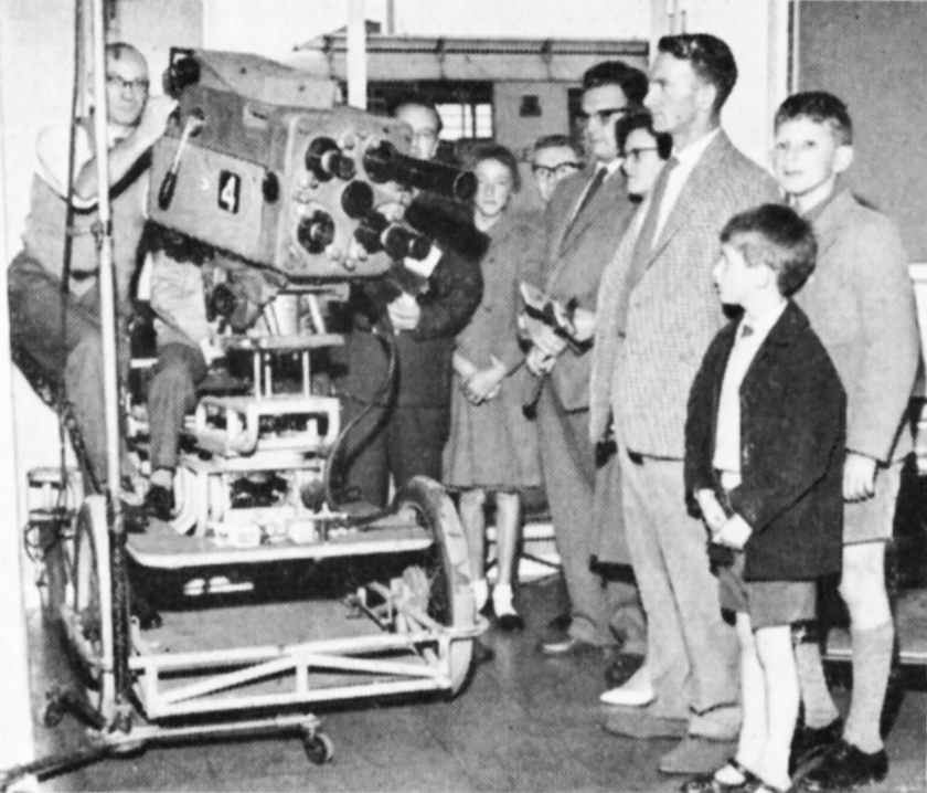
A television camera demonstrated on an open day
Failure Conditions
Quite a number of factors may interrupt the smooth flow of programmes. The most likely is the failure of signals to arrive at a transmitter due to a fault on a link or at a studio. Immediately this happens a breakdown procedure is put into operation which provides that after 3o seconds failure of sound or vision, viewers are notified, usually by the transmitter, of the condition.
Because of the need to use very high sites for the location of masts and towers, many of the transmitters are in mountainous and inaccessible places. This means access roads, connecting sites to the nearest public road, running over steep moorland with gradients of up to 1 in 5. Inevitably each winter transmitter staff are snow-bound overnight and to cater for this eventuality all stations are equipped with beds and bedding and stocks of food for a number of days.
Because of their location certain stations are used by the Air Ministry for meteorological observations and this service is an additional duty for the staff.
Visits to Transmitting Stations
Once a year, on a Saturday during the summer, the Authority’s transmitting stations are declared open to the public. Many viewers like to see at first hand the varied and complex equipment which is to be found at their “local” station: to stand at the base of a 1,000-ft. mast or 450-ft. tower; to talk to the staff; to see demonstrations of telecine apparatus; to examine the considerable array of valves; and to watch the lively and changing waveform displayed on an oscilloscope when someone speaks into a microphone. These and other displays are supported by diagrams and maps showing the national networks of transmitters and linking circuits and relief maps of the service area of the station which illustrate how the topography creates shadows or pockets of poor reception.
Partners in the everyday life of the transmitters are the studios and the G.P.O. switching centres: both of these lend support on Open Days with displays and demonstrations. Local television announcements are made when there is going to be an Open Day, and intending visitors are told how to apply for tickets.
Open day demonstrations of Goonhilly Down equipment
Riggers climb to 1,000 ft.
Adjustment of the programme input equipment at Fremont Point
Propagation and Investigation Work
The ITAs engineering group responsible for the point-to-point-link network have a sub-group which carries out experimental studies of wave propagation at V.H.F. (very high frequency) and U.H.F. (ultra high frequency). Special equipment has been designed for carrying out long-term measurements of radio propagation over chosen transmission paths. By storing the data on magnetic tape the equipment enables the rapid analysis of signal strength records over several months. Apparatus of this type was employed in Alderney, Channel Islands, for many months before a decision was taken to link the Islands with the mainland network.
Work is currently in progress on the evaluation of the U.H.F. transmissions from the BBC’s Crystal Palace station, and to do this a mobile laboratory has been equipped with monochrome and colour receivers and the appropriate measuring equipment. This vehicle and a separate field-strength measuring vehicle are at work in the London area carrying out measurements at a very large number of sites in chosen areas. This type of work is conducted from a laboratory located at the Authority’s Headquarters. This laboratory is also used for development of special receivers for measurement and programme use.
Some work is at present in progress on the development of apparatus for the measurement of mast stability. Quantitative information on this problem is urgently required in connection with those sites where it is necessary to mount highly-directional microwave link aerials on the transmitting mast. The effect of wind on these very large structures cannot accurately be predicted and rotation may cause some loss of signal on an associated link aerial. Measurements of this type are also of interest in deciding the effect of mast movement on U.H.F. transmitting aerials.
Three things are involved in bringing a good picture into your home. The first is the set, which must be capable of receiving signals transmitted by the ITA and which also must be properly tuned. You cannot expect to get a good signal on a poor or badly adjusted set. Make sure that you understand the purpose of your set controls by reading the instruction book carefully. If you live in a place where the signal strength is weak it is all the more important to buy a set of maximum sensitivity, able to make the most of it.
The second important point is the feeder cable running from the set to the aerial: these cables vary in efficiency and the use of a good quality type can be an immense advantage. The farther away the aerial is from your set, e.g., if it is on the roof, the more important it is for you to have a first-class low loss lead-in cable. Experience has shown that the reception troubles of many viewers are a result of trying to save installation charges by using poor quality lead-in cable, with the result that half the signal strength is lost before it reaches the set.
The third important point is the aerial, which must be of the proper type and correctly fitted. The majority of reception problems are attributable to the wrong selection or fitting of Band III aerials. As signals transmitted on the frequencies used by the ITA are liable to be affected by hills, tall buildings and trees the aerial must be carefully selected and positioned so that the maximum signal is received: an alteration of a degree or two in its direction can sometimes make a considerable difference in the quality of reception.
You must make sure that the aerial you use is the right one for your particular circumstances. The largest and most expensive aerial is not necessarily the best in your case. Aerials vary from simple dipoles or single rods to large arrays with two rows of nine or ten rods. Owing to the difficulties caused by obstructions between transmitter and aerial it is possible that quite different results will be achieved by the same type of aerial in houses next door to each other, or even in different rooms in the same house and different parts of the same room. It is no good insisting to your dealer that you must have the same kind of aerial as your friend next door just because he gets a good picture. You may need a quite different aerial to get a picture of the same quality. Your best plan is to put yourself in the hands of a reliable dealer and take his advice. He may have to try several different types before he finds which kind suits you best, and his knowledge of reception conditions in your neighbourhood will help him to find the right one quickly.
Another important point is the location of the aerial. If the signal is very strong a good picture can be obtained with a portable stand aerial on top of the set or some piece of furniture close to it. If the signal is weak, it may be necessary to put the aerial in the loft or on the roof. It may take two men a whole day to find the place which gives the best results. You will have to pay for their time, of course, but you will find it well worth the money to take trouble over this matter. There is not much point in buying an expensive set and then spoiling its performance to save a few shillings, and dealers are too busy to spare men to waste your money by taking an excessively long time over the job.
One of the main reasons why it is worth taking trouble over your aerial is to make sure there are no “ghosts” or double images on your picture. If your aerial picks up, in addition to the direct signal, a signal reflected from some such object as a nearby factory wall, the reflected signal will reach the set a fraction of a second later than the direct signal, and so cause a ghost. By turning the aerial slightly it is often possible to reduce the ghosting or eliminate it altogether. On the other hand, if your aerial is masked from the transmitter by an obstruction, it is sometimes possible to find a better signal than the direct one by “aiming” your aerial at a strong ghost signal reflected from neighbouring buildings which are not so masked. Using or eliminating reflected signals takes time and trouble too, but here again the result makes it worth while.
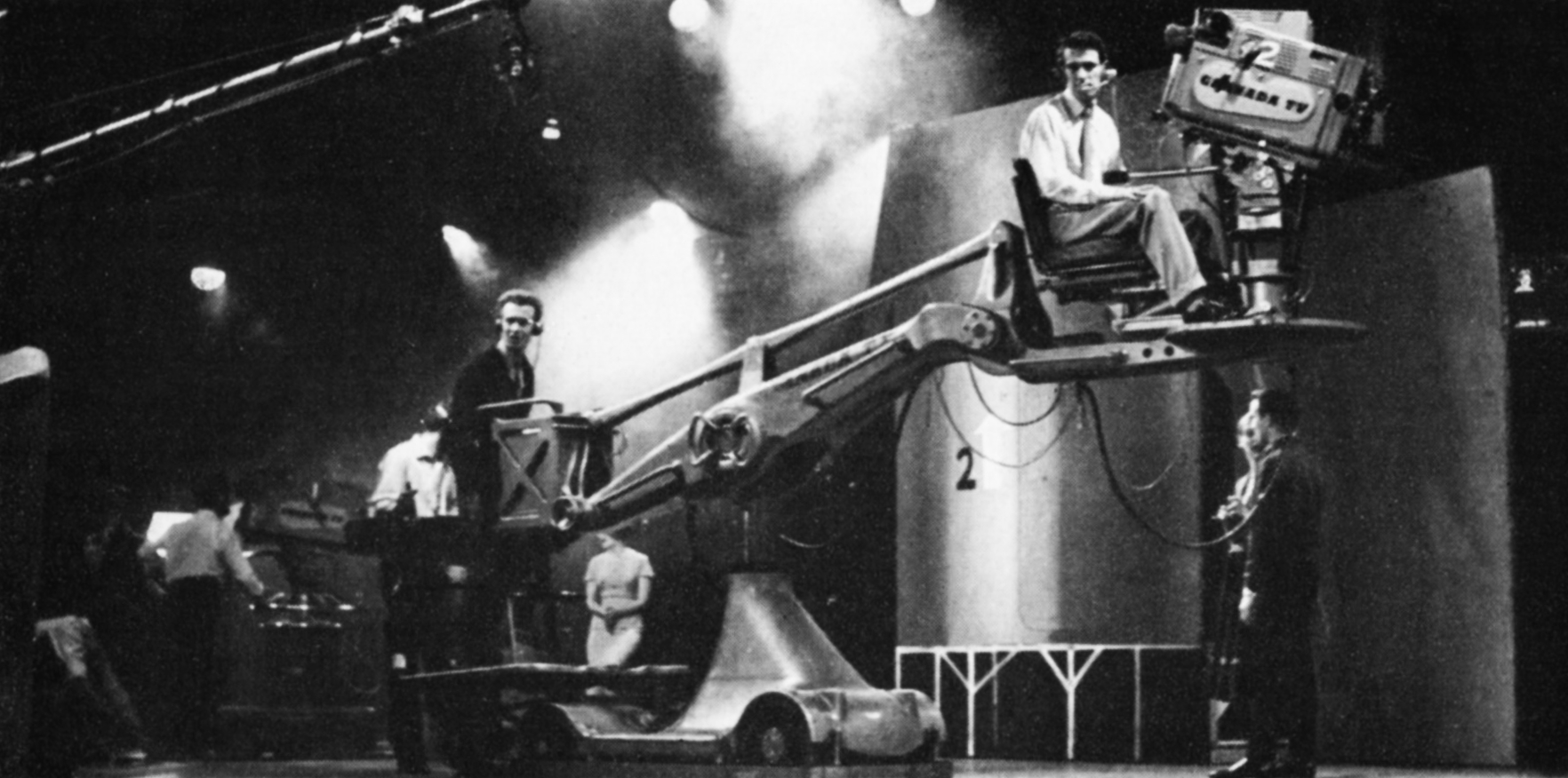
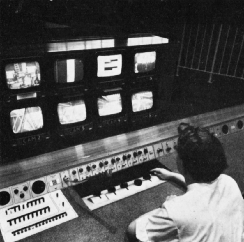
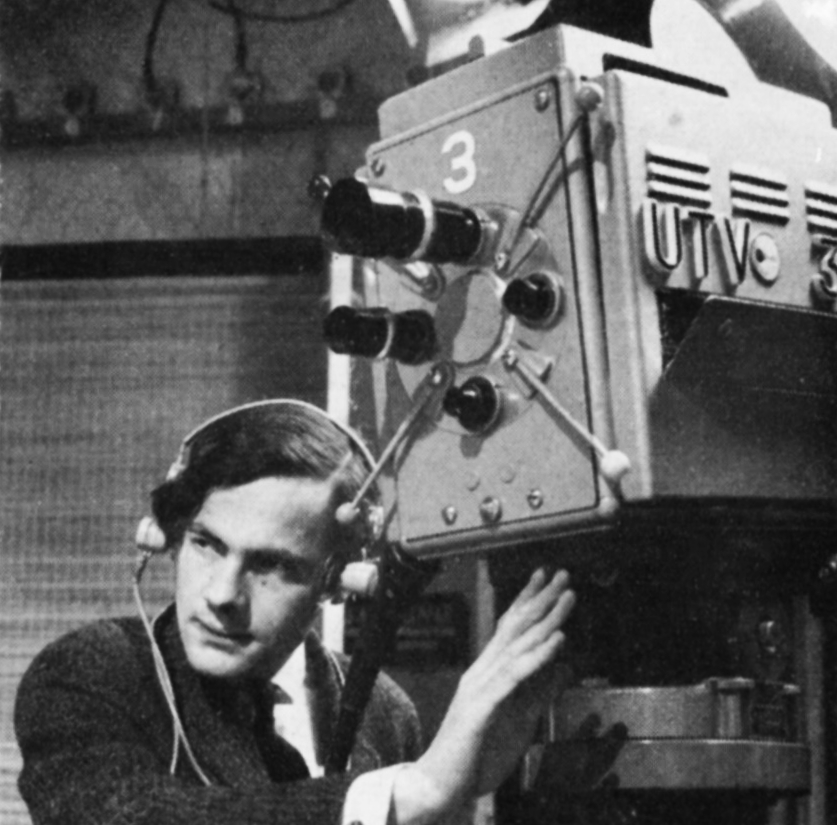
Camera crews in the studio. Granada
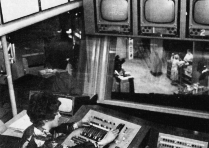
Operating the vision mixing panel in the production control room. ATV
An engineer in master control, the nerve centre of the technical area. Westward
Joystick controls are used by an engineer to balance the pictures. ABC
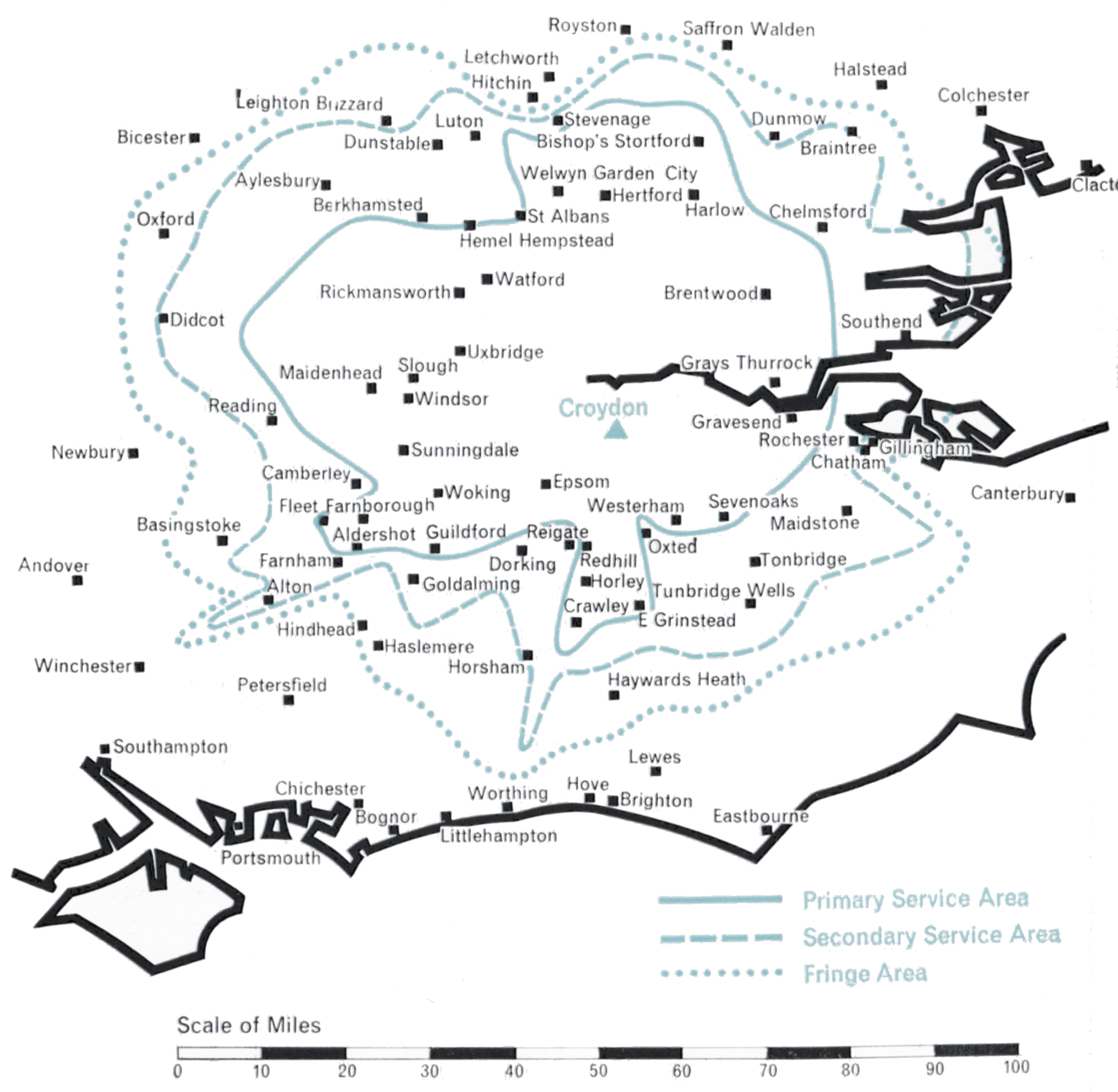
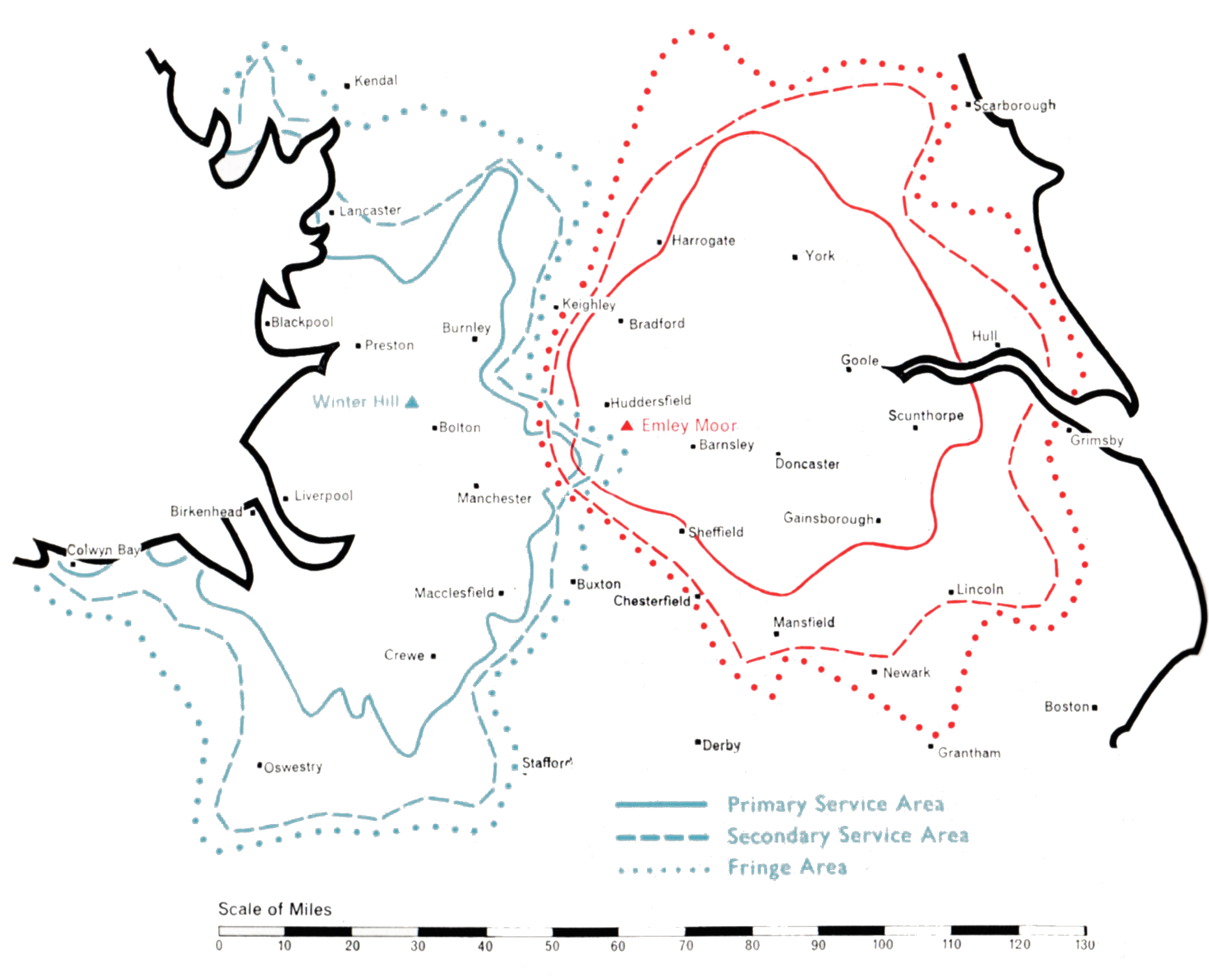
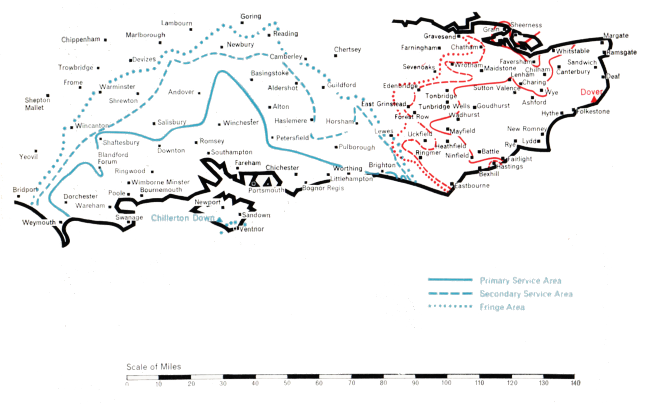
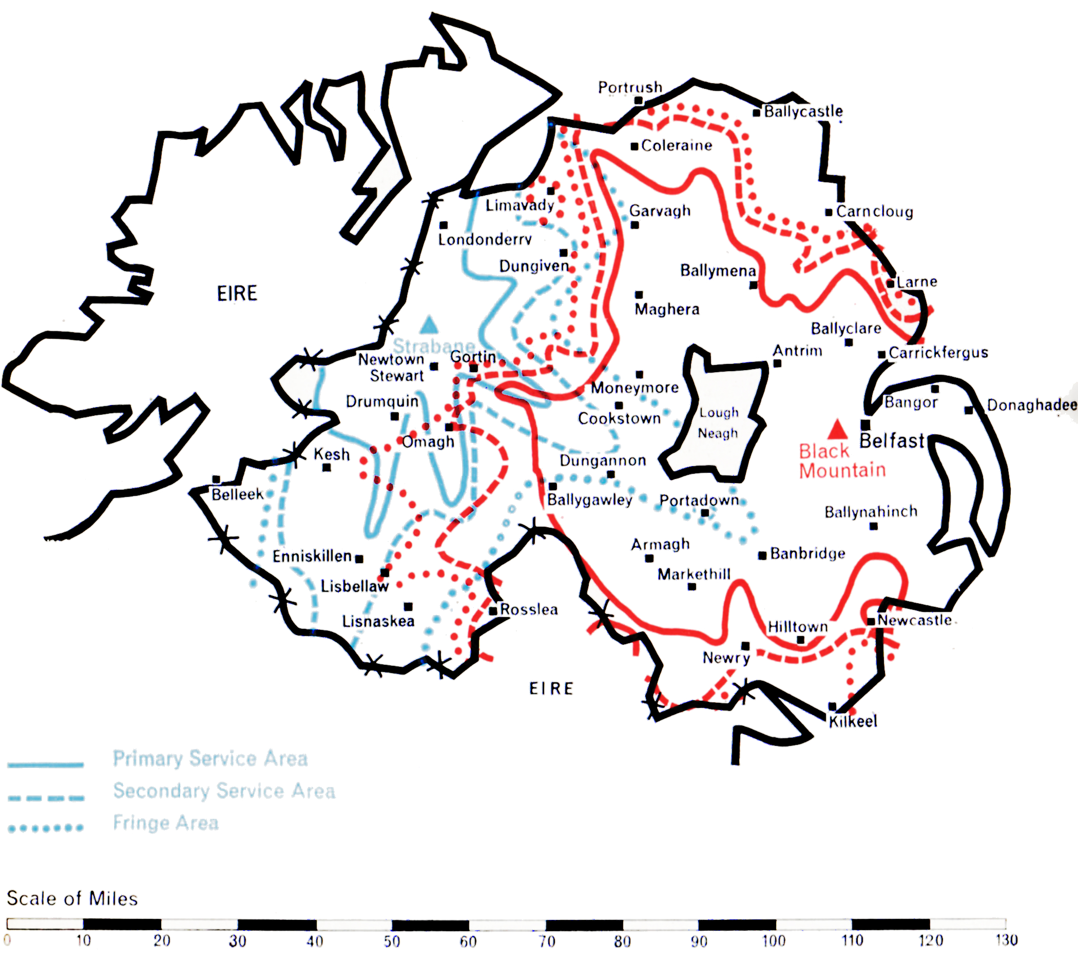
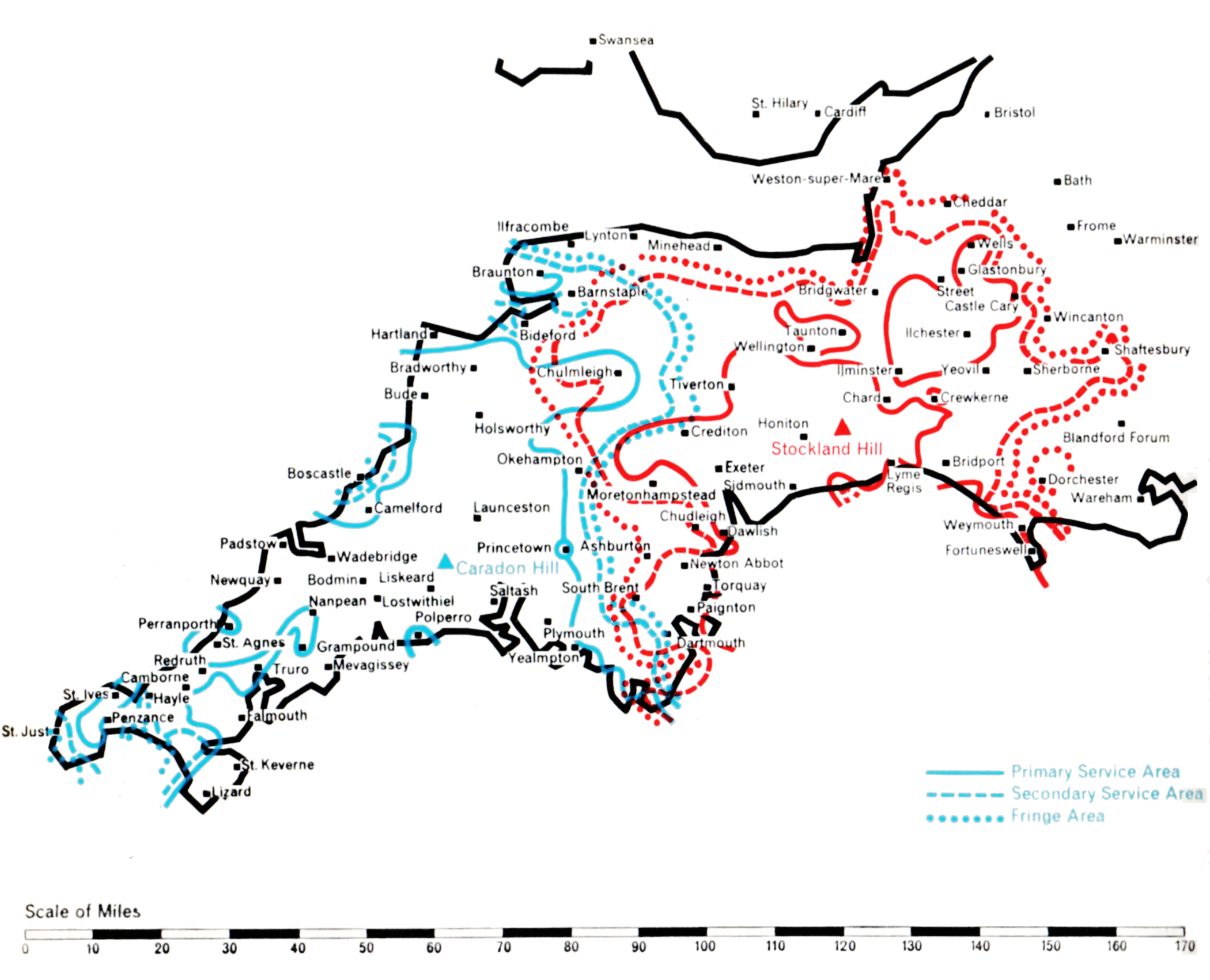
The following pages describe the coverage areas of the ITA’s transmitters, the varied problems which the Authority’s engineering staff have had to overcome in bringing Independent Television to each area of the country, and the technical details of the stations. The maps show the reception which should be available from each transmitter, on the following definitions:
PRIMARY SERVICE AREA
Within 2mV/m median contour
Where most viewers unless they are situated in particularly unfavourable positions should receive a consistently satisfactory service.
SECONDARY SERVICE AREA
Within ½mV/m median contour
Where a substantial proportion of viewers should receive a satisfactory service, but in a few unfavourably situated places reception may be poor.
FRINGE AREA
Within ¼mV/m median contour
Where acceptable reception should be secured in many locations, although this service may be subject to some interference from time to time. Some viewers living in favourable positions outside the Fringe Area may also receive a satisfactory service.
For the technical planner concerned with achieving national television coverage as economically as possible, London is the obvious point of departure. Within a radius of some forty miles from its heart live some twelve million people, almost one quarter of the total population of the United Kingdom. Topographically the London area presents no serious problem of propagation. It is relatively flat except for the North Downs some twenty-five miles to the south and the ridge of the Chiltern Hills some thirty miles to the west and north. Indeed, the difficulty is to find high ground close enough to the centre of London on which to construct a station. The choice rests between the 400 ft. ridges of Muswell Hill (Alexandra Palace) in North London and Sydenham (Crystal Palace) in South-East London.
Alexandra Palace was the BBC’s choice for their original Band I London station in 1935. Twenty years later, however, they were to move to a new station at Crystal Palace. In the interests of good planning the ITA decided to locate its first Band III station near this site, just a mile away on West Norwood Hill.
A suitable open space was found here for the construction of a small compact station which could be brought into operation with the least delay. The single 10 kW transmitter, the first Band III set constructed in this country, was a laboratory prototype and the aerial an experimental 8-stack omnidirectional vertically polarised array supported on a 200 ft. tower of virtually “stock” design. From this station on 22nd September 1955 the first programmes of Independent Television were transmitted. The effective radiated power was 60 kW (peak white vision), 15 kW (carrier sound). The potential population coverage was about 11 million people. After some months a second fully-engineered production 10 kW transmitter was installed as a standby. A little later, further equipment was installed to enable both sets of transmitters to be operated in parallel in order to double the station’s power.
It was realised that in due course the Croydon station must be given a higher tower and a new aerial system with directional characteristics tailored to give the optimum performance. Meanwhile, however, engineering effort was devoted to expanding the ITA network of stations to meet the fast-growing public demand for Independent Television programmes in other parts of the country. The completion of the BBC’s high tower at Crystal Palace allayed any fears that the mutual reflection of signals radiated from the two towers just a mile apart might be harmful to reception. Thus in February 1959 the Authority obtained Government approval to erect a higher tower and directional aerial at Croydon.
By the end of 1962 Croydon was transmitting from its slim new 500 ft. tower and radiating an effective power of about 400 kW directed to the north-west, with 5o to 100 kW e.r.p. in other directions, depending on the extent to which account had to be taken of the conflicting requirements of topography and co-channel interference with other ITA stations or with the television services of other countries. With its improved performance Croydon is bringing the programmes of Independent Television to a population of nearly 13 million in the London area, including some half a million viewers who have not before received any satisfactory ITV service.
The first proposal for covering the great Northern area with its population of about thirteen million was to build a high-power transmitting station close to the existing BBC Band I station at Holme Moss on the high central rib of the Pennine Chain. Studies showed that this would have been technically attractive had it been possible at that time, without a very considerable delay for special development, to provide an effective radiated power of about 500 kW with a mast height of at least 1,000 ft. Even so, severe fading would undoubtedly have been experienced at the fringes of the service area, on the west coast at Liverpool and on the east coast at Hull.
These and other considerations led the Authority to conclude that the area would be served best by two transmitting stations, one on the western slopes of the Pennines to serve Lancashire, Cheshire and parts of Staffordshire, and another on the east side of the Pennines to serve Yorkshire. The Postmaster-General agreed to this proposal, which constituted the first of several departures from the general principle that Band III stations should be sited close to existing Band I stations. The quality of service which has been given to the North of England as a result of this departure has fully justified the decision. Winter Hill, the Lancashire station, was constructed on the summit of Rivington Moor, a fine site 1,450 feet above sea level. The aerial, which is carried on a self-supporting 450 ft. tower radiates 100 kW omnidirectionadly. Construction work began in September 1955 and the station went into programme service on 3rd May 1956.
Winter Hill
The selection of the site for the Yorkshire station posed considerable problems largely because coverage of the main concentration of population within the hill-shadowed towns of the West Riding had to be combined with the provision of a service as far away as Kingston-upon-Hull some 5o miles away across the Yorkshire Plain.
Sixteen different sites were studied theoretically and tests, using a balloon transmitter, were made at four of them before Emley Moor, 850 feet above sea level on the eastern slopes of the Pennine Chain, was finally selected. Once again, because of the small area available, a 450 ft. tower was used to support the aerial, which has a semicircular power-radiation pattern delivering 200 kW e.r.p. in all easterly directions but only a few kilowatts backwards to the west into the natural barrier of the Pennines, thus preventing waste and an unnecessary overlap with the service area of the Winter Hill station. Emley Moor went into service on 3rd November 1956.
Chillerton Down was the first of the two stations built to serve the south and south-east coastal areas of Britain. It was designed to cover central southern England, the important agricultural and holiday area along the coast from Weymouth in the west to Brighton in the east, together with the great ports of Southampton and Portsmouth and, inland, the county of Hampshire and adjoining parts of Dorset and Wiltshire. A BBC Band I station existed at Rowridge, on the Isle of Wight. In conformity with the Government’s policy the Authority decided if possible to build its Band III station close to Rowridge. The site selected was on Chillerton Down, 550 ft. above sea level on the south side of the island. Opposition to a second television mast on the island was raised on grounds of amenity. However, the alternative of building at Rowridge a more massive and commanding tower to carry both the ITA and BBC television services and the BBC’s VHF sound services proved even less welcome, and the Authority’s proposal to use Chillerton Down for a slim 750 ft. mast was accepted.
Chillerton Down
The transmitting aerial has a semicircular power-radiation pattern, oriented to direct 100 kW in both directions along the coast as well as landwards, but radiating very low power across the English Channel to prevent interference with the services of Radiodiffusion-Télévision Francaise. Chillerton Down went into service on 30th August 1958 and serves the intended area well.
The sister station at Dover presented unusual problems. The general requirement was to serve the south-east corner of England not covered by Chillerton Down or Croydon. The site of the station was determined by the need to serve Folkestone and Dover, which lie at sea level under high cliffs. The solution was to build the station on the high cliff road linking the two towns. Church Hougham, 450 feet above sea level, was used and from a 750 ft. mast a signal could be directed into both towns. At the same time the station had to link up with the service area of Chillerton Down beyond Eastbourne, 5o miles west along the coast. 100 kW was sufficient to provide an adequate service for Eastbourne and the intermediate coastal towns, and there were no inhibiting power restrictions. Northward, to serve the towns on the Thames estuary not covered by Croydon, 10 kW to 20 kW e.r.p. was adequate. However, viewers in France had to be protected from interference to their reception of the signal from the Rouen station. Calculations showed that Dover must restrict its power to less than 1 kW over an arc of 90° towards the French Coast. It was no mean task to construct a transmitting aerial to do this, and at the same time to radiate 100 kW westward. Test transmissions were made for many weeks, during which the Authority’s engineers developed a measuring technique, using a helicopter, to check the the radiation pattern of the transmitting aerial. This difficult operation accomplished, Dover went into service on full power on 31st January 1960.
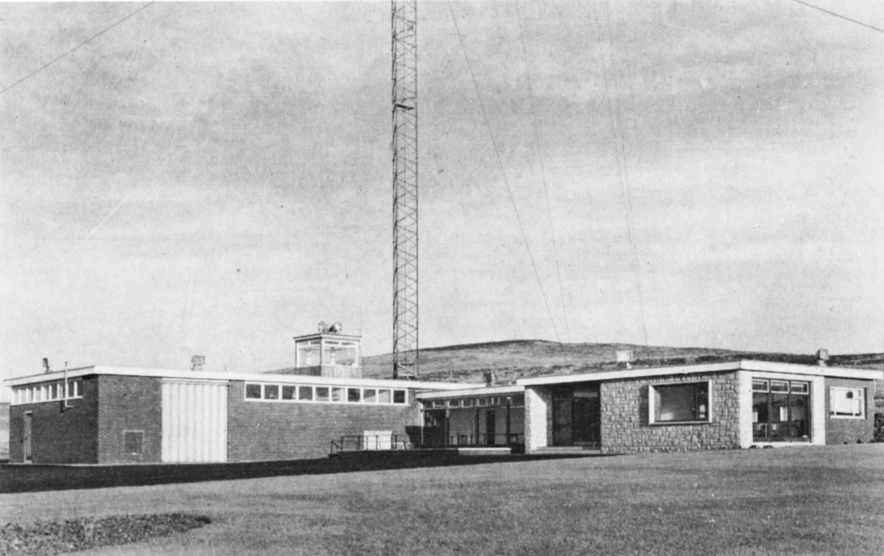
A large part of Northern Ireland was provided with an Independent Television service in the Autumn of 1959 by the construction of the Black Mountain station near Belfast, close to the BBC’s existing Band I station at Divis. However, West Ulster, which includes the districts of Londonderry and Enniskillen, could not be covered by this station and, clearly, at least one additional station was needed.
The Black Mountain station overlooks Belfast and is 987 ft. above sea level. A 750 ft. mast, the highest permitted by the Ministry of Transport and Civil Aviation due to the proximity of the airport, was erected. It supports a moderately-directional aerial radiating about 100 kW to both the north-west and the south-west, 7o kW to the west and 20 kW to the east. This power-radiation pattern ensures the optimum coverage of the area whilst avoiding harmful interference to the service areas of other stations using Channel 9, notably Winter Hill.
Black Mountain
A study of the topography of West Ulster revealed that the unserved area could economically be covered by a single station if a high site near Strabane could be obtained. A site 900 ft. above sea level was found four miles south-east of Strabane and here a station using a 1,000 ft. mast was constructed.
It has a highly-directional aerial radiating about 9o kW in two main lobes to the north and to the south. 10 kW only is radiated to the east and west, but this suffices to cover the areas not served by the Black Mountain transmitter and, at the same time, prevents unnecessary radiation into the territory of the Irish Republic to the west.
The Black Mountain station went into service on 31st October 1959. Strabane began programme transmission during February 1963.
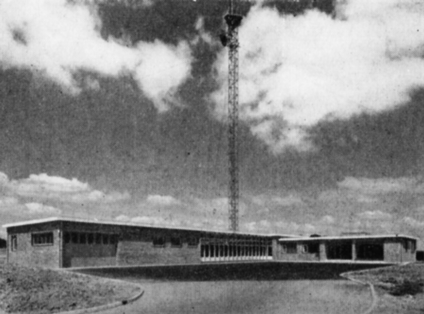
Propagation studies of the best method of covering the 150 mile long wedge-shaped area of Devon and Cornwall showed that it was not practical to serve it adequately from a single Band III station centrally situated on the heights of Dartmoor, adjacent to the BBC’s station at North Hessary Tor. Government agreement was obtained to build two stations, one in Cornwall and one in South Devon, another necessary departure from the principal of co-siting with the BBC Band I station.
High sites were found at Caradon Hill, near Launceston, for Cornwall; and at Stockland Hill, near Axminster, for Devon. Transmitting aerials with highly-directional lobes were engineered to give the desired grade of service to both areas while minimising interference with other ITA and Continental stations which use the same channels. Each station needed a 750 ft. mast to minimise “shadows” in this hilly terrain.
Stockland Hill
For Caradon Hill, the requirement was to give a service to the whole of Cornwall west of Dartmoor and reaching to the extremity of England at Land’s End. A power of 200 kW e.r.p. was beamed in this direction but to avoid interference in the service area of the Dublin station the power over an arc of 40° to the north-west had to be restricted to a mere 10 kW, while to the south the power had to be restricted to 25 kW to avoid interference in the service area of the Cherbourg station.
Studies showed that in order to cover Devon while not overlapping unnecessarily with the existing service area of St. Hilary, Stockland Hill should direct its maximum power in two lobes, one north-west towards Barnstaple and the other south-west towards Dartmouth. 100 kW was the maximum permissable radiated power but restriction to 10 kW eastwards was necessary to prevent interference in the London area, which also uses Channel 9. The shape of the aerial radiation pattern thus became that of a boomerang facing westwards
A subsidiary beam of about 5o kW directed south-east towards the island of Alderney was also desirable to ensure reliable reception of the Stockland Hill signal in the island, in order to relay the mainland programmes by Post Office microwave link to the Fremont Point station in Jersey for rebroadcasting in the Channel Islands. However, the service area of the existing French station at Bourges had to be protected and the power radiated towards Alderney was restricted to 20 kW. Fortunately, in practice, this power is just sufficient for the Stockland Hill signal to be received in Alderney, with a signal to noise ratio good enough for rebroadcasting from the Fremont Point station. Both stations went into service on 29th April 1961.