


The day at one of the Authority’s transmitting stations normally begins at 8 a.m. and ends soon after midnight, but when necessary work continues throughout the 24 hours.
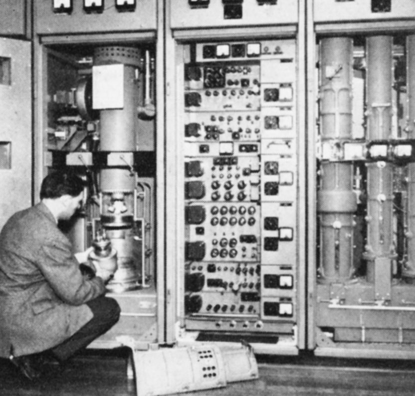
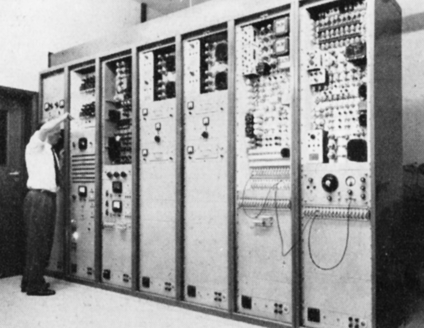
From the arrival at the transmitter of the morning shift of two or three engineers there is about two hours before due station goes on the air at 10 a.m. The most important task is to prove that the two sound and two vision transmitters are fully operational. The power output, frequency response, linearity, noise content and so on must be checked, involving the use of complex and specialised test equipment.
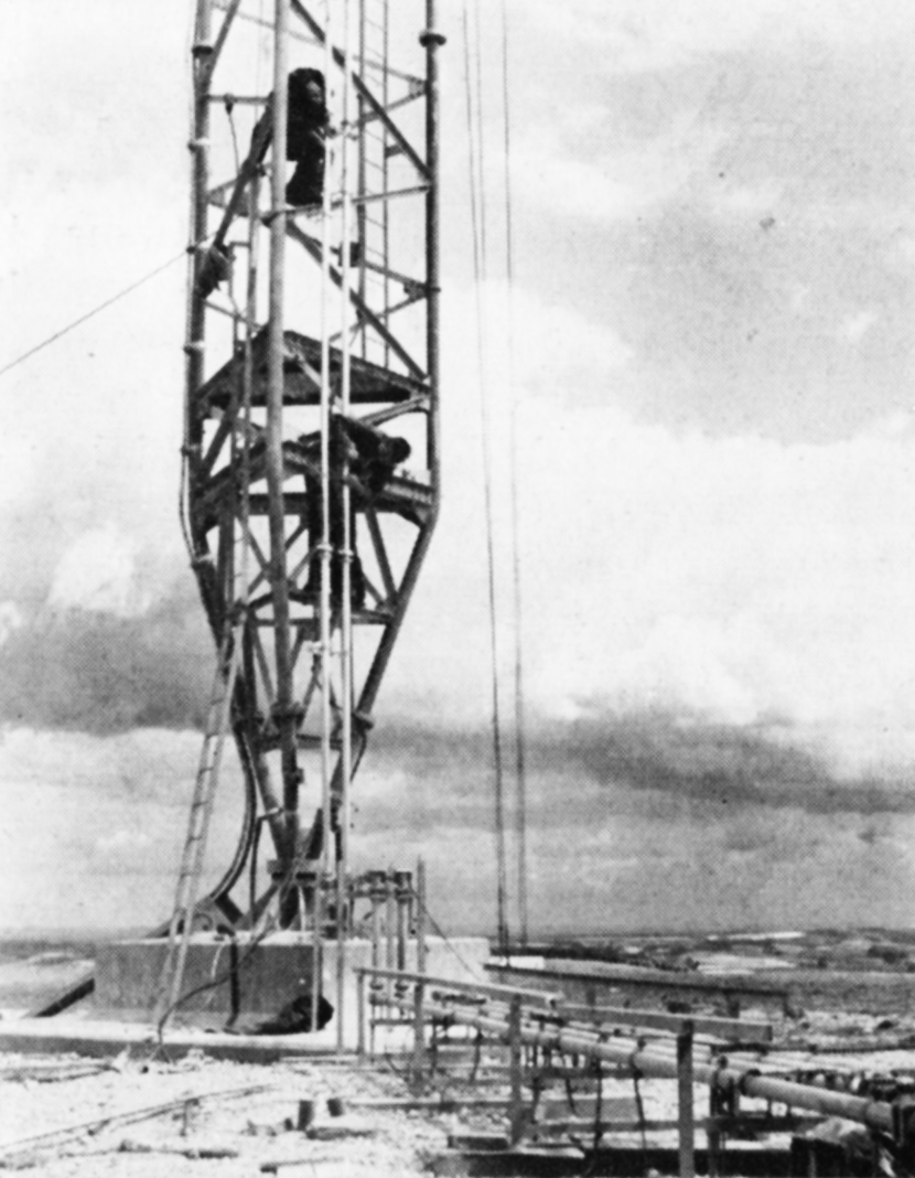
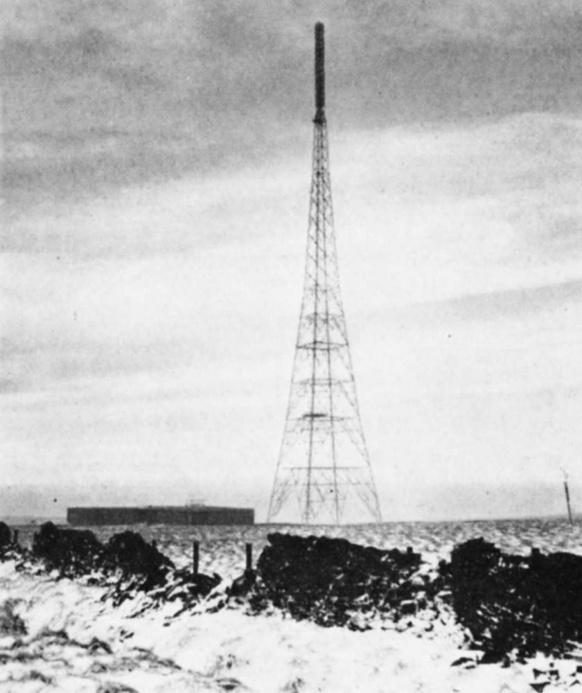
The masts and towers, which vary in height from 450 ft. to 1,000 ft., must be ascended regularly by riggers and climbing electricians to check the structure, aerials, feeder systems, aircraft obstruction lights, the aerial de-icing heaters or plastic covers which prevent ice formation on aerials, and other fittings. Certain of this work can only be done when the transmitters are closed down and, in consequence, it is performed between dawn and 10 a.m.
Trade Transmissions
On weekdays from 10 a.m. a regular schedule of transmissions is provided, primarily for the benefit of the retail trade. The pattern is as follows:
          Vision             Sound
10.00     Test Card “C”      400 c.p.s. tone
10.05           “            Silence
10.06           “            Music
10.30     Still Scene        400 c.p.s. tone
10.35           “            Silence
10.36           “            Music
10.45     Test Card “C”       “
11.00     Still Scene        400 c.p.s. tone
and so on until 15 minutes before the start of programmes. A similar schedule is observed by the BBC, but when the ITA stations are showing a test card the BBC displays a scene. Programme commitments permitting, this ensures that during test periods the trade are able to see a test card on one or other channel at any time. The test card and the sound are used by the trade for the alignment of aerials, and for setting-up and checking receivers. The still scenes are used for receiver demonstration purposes. The short intervals of silence in sound are for checking the receiver noise level.


During trade transmissions much work is undertaken at the stations. If only one transmitter unit is in operation certain routine maintenance work is possible on the other, and this work – which according to a schedule may be of minor or major magnitude – is always to be done. In this way equipment is held at a high operational standard so that the maintenance work is very largely of a preventive nature. A typical station uses 1,500 valve sockets and when new valves of the largest and most powerful size are delivered these must be tested under working conditions. Altogether some 200 different types of valve are used.
The majority of stations are served by the various Electricity Supply undertakings by two differently routed feeders, one standby for the other. Where this is not possible, a diesel-driven alternator generally supplements a single feeder, and to maintain it in known running order it is used to power the station during trade transmissions.
Each vision and sound transmitter generates a carrier wave upon which is emplanted the signal from the camera or the microphone. It is this carrier which conveys the signals from the transmitting aerial, through the ether, to the viewers aerials and receivers. Because ether space is limited the Authority’s Band III transmitters share channels and in consequence the carrier wave frequency must be very constant, to an accuracy of ±2.5 parts in a million. It is, of course, necessary regularly to measure the carrier wave frequencies and, in the Authority, this is done at two of the transmitting stations, Lichfield and Black Hill. At these two stations, before 10 a.m. or at midday, the transmitters are switched off and the transmitting aerials at the top of the 1,000 ft. masts are used as receiving aerials for the other transmitters which are located around them – some up to 200 miles away – and the received carriers are measured by special equipment.
On certain days of the week comprehensive checking of the national vision and sound links, and local sections, is undertaken. Test signals are principally originated either in London or Manchester and pass over the network to all centres where they are measured and recorded. Each test occupies one to two hours from 10.30 a.m.

Daily Programmes
The time of commencement of the daily programmes depends upon the day of the week and the location of the transmitter, but the pattern is similar. The first programme may be for schools, a racing outside broadcast, or a lunch-hour feature, and it may be followed by other items interspersed with trade transmissions before the commencement of the continuous evening schedule. Prior to any programme the links between studio and transmitter must be proved by the passing of test signals in vision and sound, and transmitters must be adjusted to the correct modulation condition. Studios, G.P.O. switching centres and transmitters must work to a common time standard to the nearest second, and this is achieved by all concerned setting clocks to TIM. The final precaution before moving into programme is to check standby equipment in sound and vision – disc turntables, tape recorder, telecine (where provided), and caption scanner.
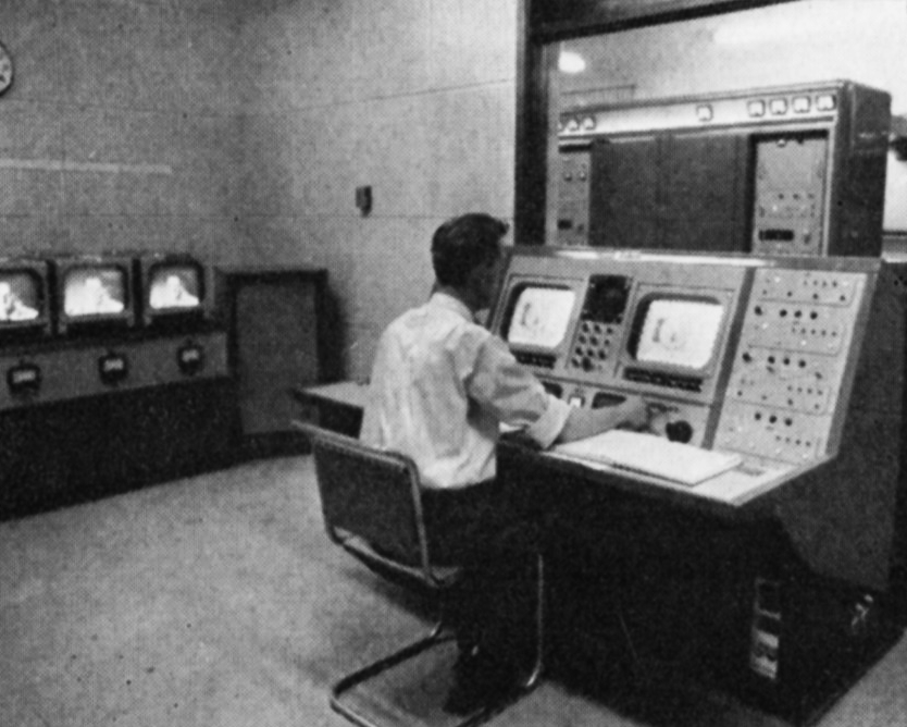
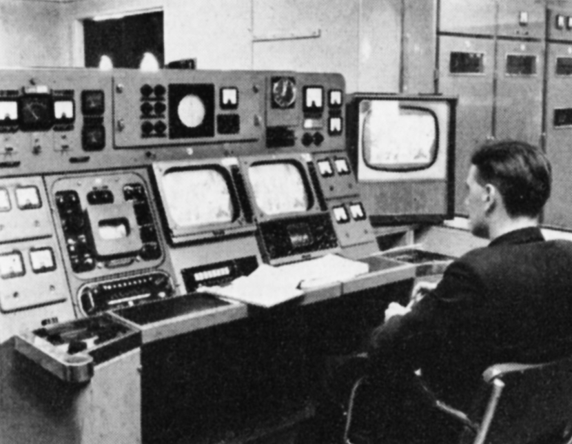
Once programmes have begun, the transmitter control room is the focal point for operations. Picture and sound must be continuously monitored for technical quality, and any point of interest noted in a log. For monitoring to be performed at a worthwhile standard, in vision a considerable knowledge of studio techniques and equipment is needed, such as an appreciation of the special characteristics of camera tubes, videotape recorders, and film. In sound, in addition to quality checking, each type of programme – music, variety or talks -should conform to a specified dynamic range.
It is important for the control room engineer to ensure that the signals suffer no degradation in passing through his station equipment, and this means that at least two picture monitors must be observed, which display the received signal and the transmitted signal; if a satellite transmitter is tied to the staffed station this also must be monitored.
Outside the control room, there is regular checking of all equipment, of the working temperature of bearings of rotating machinery, of the cooling air pressures, of the water flow, of the degree of reflection of radio frequency power from the mast-head aerials – particularly to be observed in snow storms or during ice-formation conditions – and of the red mast obstruction lights.

Failure Conditions
Quite a number of factors may interrupt the smooth flow of programmes. The most likely is the failure of signals to arrive at a transmitter due to a fault on a link or at a studio. Immediately this happens a breakdown procedure is put into operation which provides that after 3o seconds failure of sound or vision, viewers are notified, usually by the transmitter, of the condition.
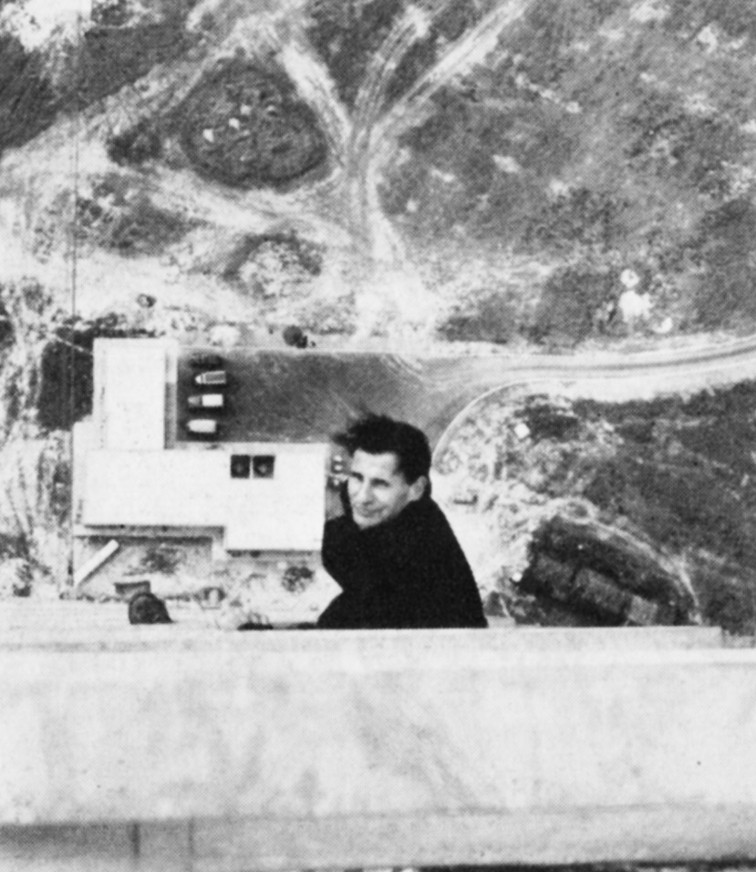
Because of the need to use very high sites for the location of masts and towers, many of the transmitters are in mountainous and inaccessible places. This means access roads, connecting sites to the nearest public road, running over steep moorland with gradients of up to 1 in 5. Inevitably each winter transmitter staff are snow-bound overnight and to cater for this eventuality all stations are equipped with beds and bedding and stocks of food for a number of days.
Because of their location certain stations are used by the Air Ministry for meteorological observations and this service is an additional duty for the staff.
Visits to Transmitting Stations
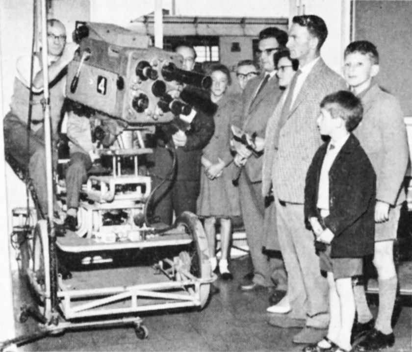
Once a year, on a Saturday during the summer, the Authority’s transmitting stations are declared open to the public. Many viewers like to see at first hand the varied and complex equipment which is to be found at their “local” station: to stand at the base of a 1,000-ft. mast or 450-ft. tower; to talk to the staff; to see demonstrations of telecine apparatus; to examine the considerable array of valves; and to watch the lively and changing waveform displayed on an oscilloscope when someone speaks into a microphone. These and other displays are supported by diagrams and maps showing the national networks of transmitters and linking circuits and relief maps of the service area of the station which illustrate how the topography creates shadows or pockets of poor reception.
Partners in the everyday life of the transmitters are the studios and the G.P.O. switching centres: both of these lend support on Open Days with displays and demonstrations. Local television announcements are made when there is going to be an Open Day, and intending visitors are told how to apply for tickets.

Propagation and Investigation Work
The ITAs engineering group responsible for the point-to-point-link network have a sub-group which carries out experimental studies of wave propagation at V.H.F. (very high frequency) and U.H.F. (ultra high frequency). Special equipment has been designed for carrying out long-term measurements of radio propagation over chosen transmission paths. By storing the data on magnetic tape the equipment enables the rapid analysis of signal strength records over several months. Apparatus of this type was employed in Alderney, Channel Islands, for many months before a decision was taken to link the Islands with the mainland network.
Work is currently in progress on the evaluation of the U.H.F. transmissions from the BBC’s Crystal Palace station, and to do this a mobile laboratory has been equipped with monochrome and colour receivers and the appropriate measuring equipment. This vehicle and a separate field-strength measuring vehicle are at work in the London area carrying out measurements at a very large number of sites in chosen areas. This type of work is conducted from a laboratory located at the Authority’s Headquarters. This laboratory is also used for development of special receivers for measurement and programme use.
Some work is at present in progress on the development of apparatus for the measurement of mast stability. Quantitative information on this problem is urgently required in connection with those sites where it is necessary to mount highly-directional microwave link aerials on the transmitting mast. The effect of wind on these very large structures cannot accurately be predicted and rotation may cause some loss of signal on an associated link aerial. Measurements of this type are also of interest in deciding the effect of mast movement on U.H.F. transmitting aerials.